
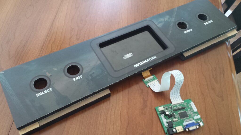
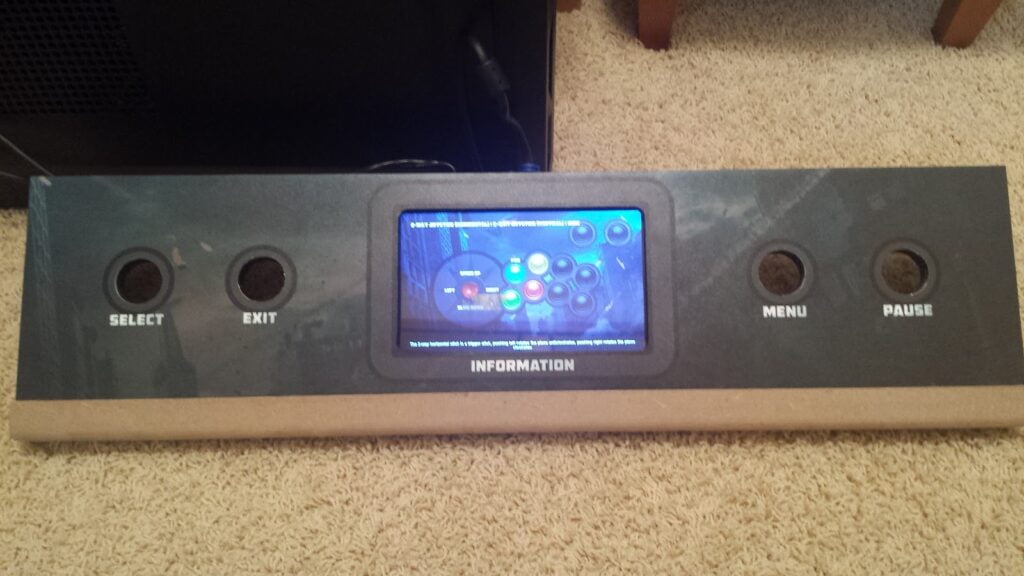
My cabinet has an administration panel below the monitor, which offers basic navigation functions for starting / stopping games. It also has a 7″ LCD that displays the controls for the current game.
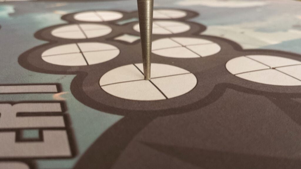
First, I cut a 1/2″ MDF sheet to the appropriate dimensions. Then, I clamped a printout of my artwork to the MDF and I marked the centers of the buttons and the screen with a center punch (the picture below is actually from the control panel, but the same process applies).
I also cut out a piece of Plexiglas to the same dimensions as the MDF. While the art I’m using is actually quite sturdy and doesn’t need Plexi to protect it; I want to keep dust and hands away from the LCD.
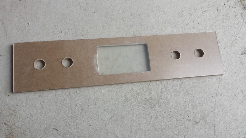
I drilled pilot holes through the MDF with a small drillbit where I center punched the button holes. Then I clamped the MDF to the Plexiglas, and drilled through both at the same time using a 1-1/8″ forstner bit.
I marked out the dimensions of the screen opening on the MDF, and roughly cut it out with a jigsaw. Using a router (with straight-edged pieces of MDF clamped to my work as a template) I routed the final edges of the screen opening. (I also had to use some MH Ready Patch to correct a router mishap, as you can see below).
I then used my router to create an inset on the back that the screen could drop into. This took a fair amount of measuring and fiddling with paper patterns, as the bezel is sized differently on each side of the screen.
NOTE: At this point, I ordered the final prints of my artwork online. When they arrived, I discovered that their dimensions were slightly different than the printout I used to drill/cut my openings. So, I actually had to re-do everything shown above (I also had to re-drill my control panel, which is covered in a future post). The moral of the story is that I’d suggest either using your final artwork to mark where you want to drill/cut; or get a cutting template from the same printer where you’ll get your final art from.
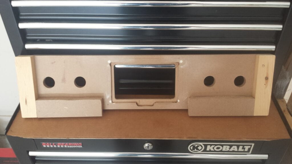
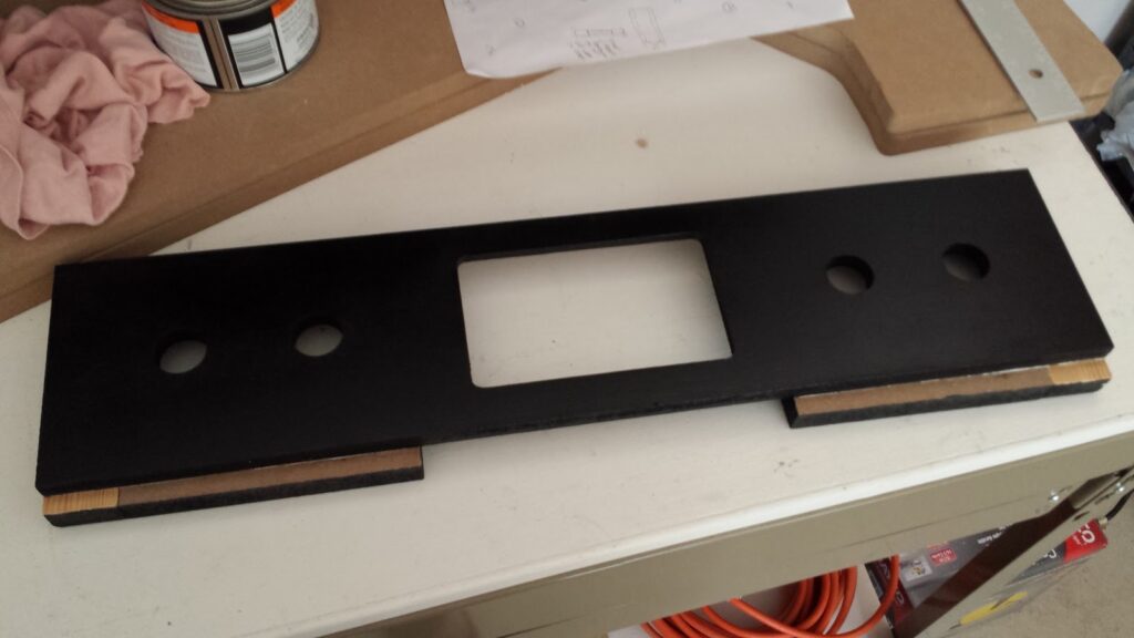
With v2.0 of my AP completed, I attached furring strips to the outside edges. These will be used to attach the AP to the cabinet’s side panels. I also attached some scrap pieces of MDF to the bottom edge, which will give me an attachment point for the bottom trim piece on the access panel.
I taped off (most) all sections that would be glued to other pieces of the cab, and primed the AP with Kilz primer (from a spray can).
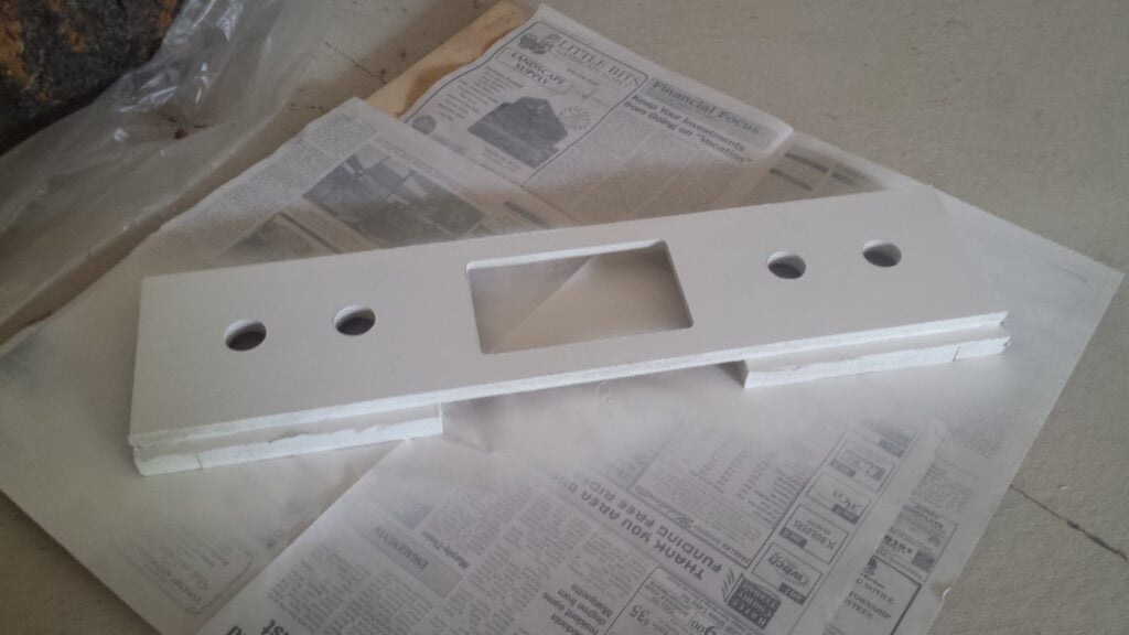
After letting it dry, I sprayed it with satin-finish black spray paint. The only part that’ll really be visible is the inside edge of the screen cutout, so I made sure to sand that section smooth with fine sandpaper between the primer and paint. I also gave the front surface a cursory sanding, just to make sure the surface was adequately smooth to attach the art overlay.
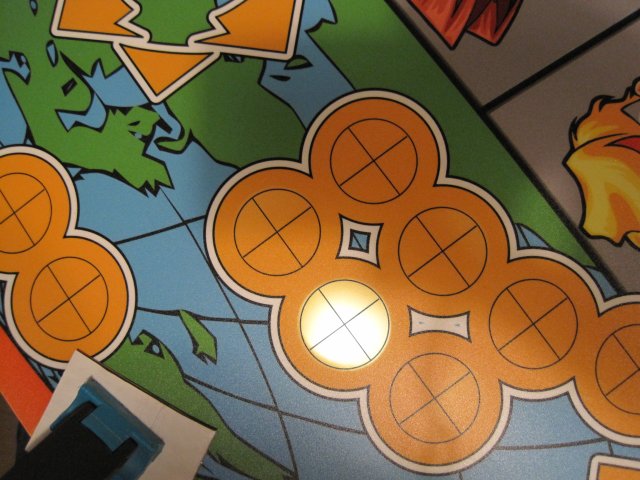
After allowing a few days for the paint to fully cure, I attached the admin panel art, which I had purchased from GameOnGraphix. By shining a light through the artwork, I was able to correctly align the button holes on the AP. The picture below is from user EMDB at ArcadeControls.com, showing how it’s done. Luckily, if you’re off by a bit on your first try, you can peel the art off the MDF and reattach it correctly.
Once the overlay is attached, I used a sharp X-Acto Knife to cut around the edges. This actually scraped some of the black paint off the inside of the screen cutout, exposing the white primer. This was easily fixed with a black Sharpie.
EDIT (10/19/2016): When I originally completed this project, I was disappointed by how hard it was to see this screen. Since I was looking down at it from an indirect angle, it was almost impossible to read without stooping down so the screen was closer to eye level. Almost a year later, I realized that I could greatly improve the visibility of the screen by flipping it upside-down, and then setting the video drivers on my PC to flip the image right-side up again. I had to do some awkward Dremeling on the back of the admin panel to get it to fit, but it’s way better now. So, be sure to check the viewing angles on your monitors before you mount them. You might find that they look a whole lot better upside-down.
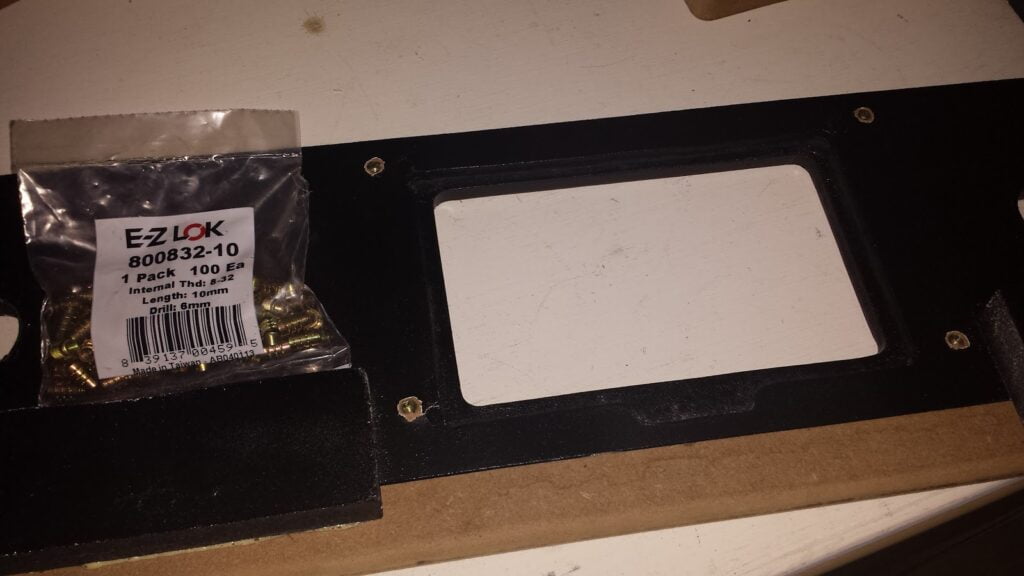
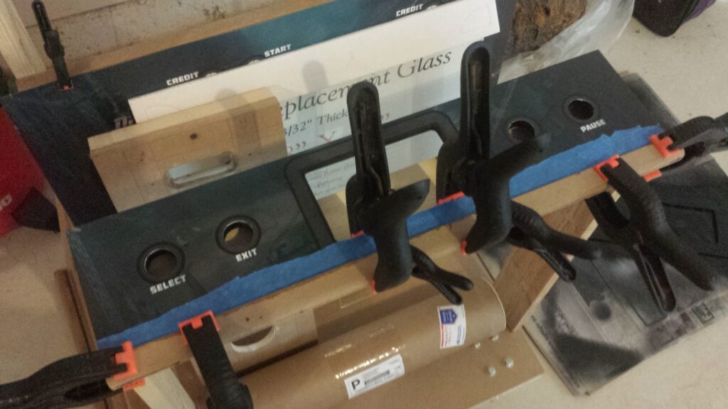
To keep the screen in place, first I cut a piece of 1/4″ MDF to size and primed & painted it. Then, I clamped it to where it would be mounted on the back of the AP, and drilled through both the retainer, and just slightly into the AP itself.
I wrapped electrical tape around all but 0.4″ of a 15/64″ drill bit, so that’s the furthest it could drill (I don’t have a drillpress where I can set the drilling depth). Then, I drilled 0.4″ deep holes into the back of the AP, and screwed EZ-Loks into the holes. This allows me to screw/unscrew the screen retainer as many times as I want.
On one side of the screen retainer, I attached the PCB for the 7″ screen using “L Type PCB feet” found on eBay.
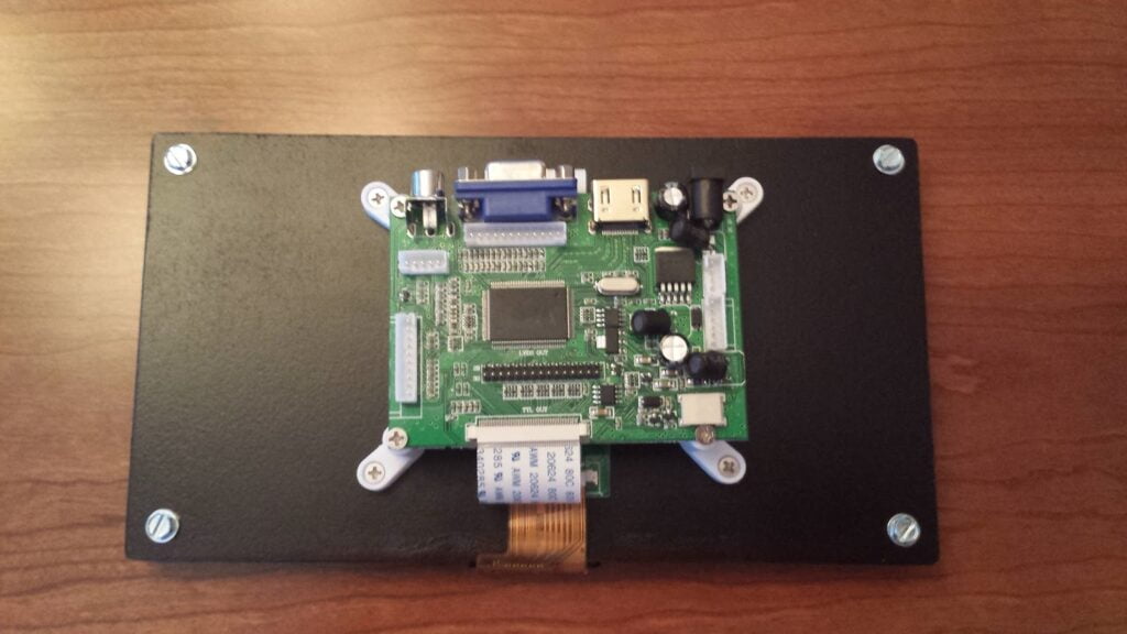
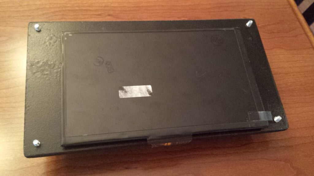
On the other side, I attached the screen with Velcro tape. Now, when I remove the retainer, all of the screen components come out in one easily-manageable piece.
Before attaching the AP to the cab, I had just one last trim piece to glue on using Gorilla Glue with plenty of clamps. (The top AP trim piece is actually a part of the main monitor bezel.)
The trim piece will be painted with the rest of the cab. Aside from that, the administration panel is basically completed.
I love the idea of the small screen showing the current controls. What software do you use for it?
Thanks! I used CPWizard to show the controls.
Technically, you're supposed to be able to set it up to show the controls on the fly using a controls.dat file. I couldn't get it working that way, so I actually used CPWizard to batch-output a PNG file for every ROM. Then, I have my frontend program, GameEx, configured to show the corresponding PNG based on the current game.