
Here, I outline how I assembled the control panel for my arcade cabinet.
A fair amount of effort went into the control panel. I tested several mock layouts on paper until I found one that I liked. Slagcoin.com is basically the online bible of arcade button layouts, and I made full use of it.
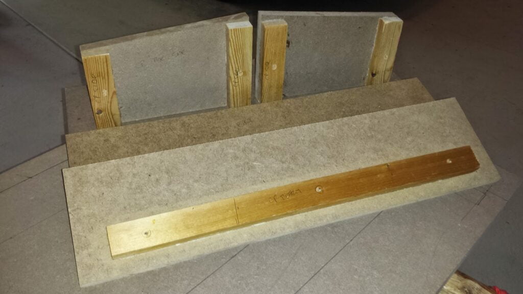
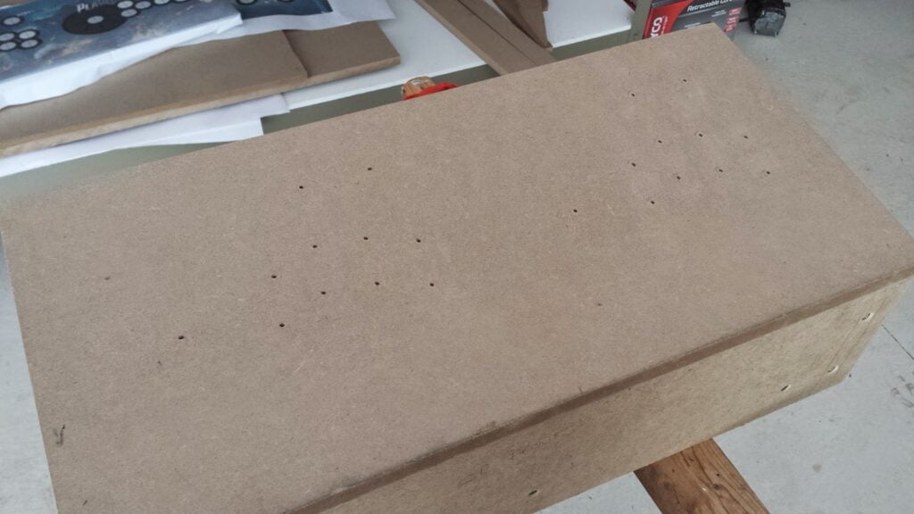
I started by cutting out the six sides of the control panel box, and attaching furring strips to keep them together. I screwed and glued the strips on, screwing through the MDF and into the furring strips (since the wood of the furring strip will do a better job gripping the threads at the end of the screw than the MDF).
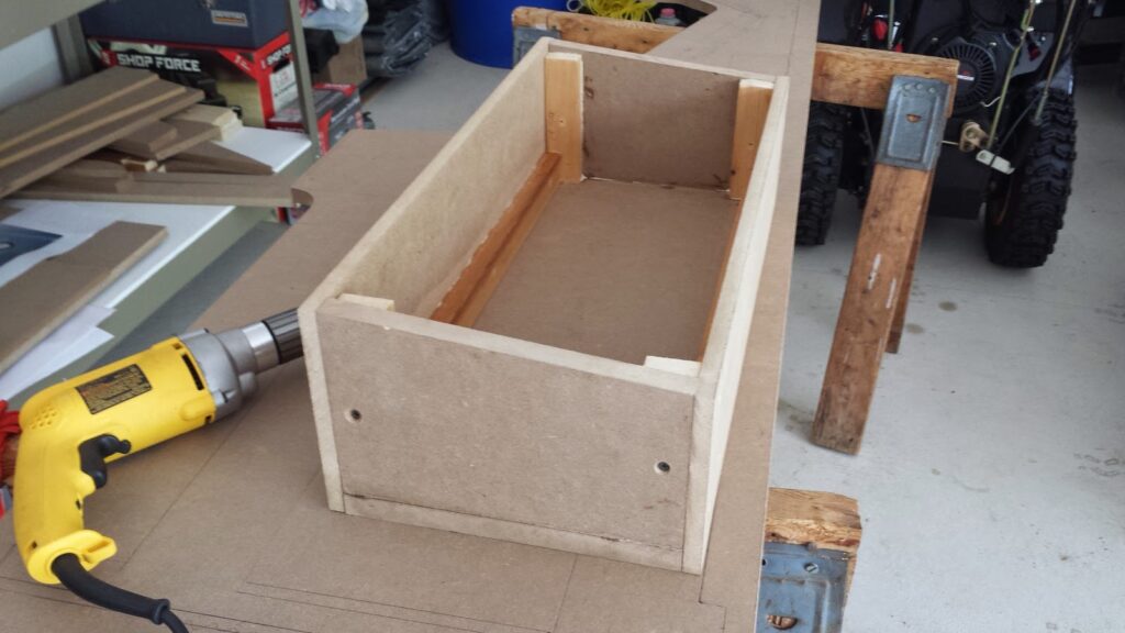
Then I glued & screwed all the pieces together. The top is not attached, since it will be detachable on the finished product. And the back panel also isn’t actually screwed on for now, because I need to be able to access the underside of the top panel to formulate some kind of latching system. (Ultimately, I never actually made a latching system, and the control panel simply rests snugly in place. Having the back panel detached did help immensely with the wiring process, however.)
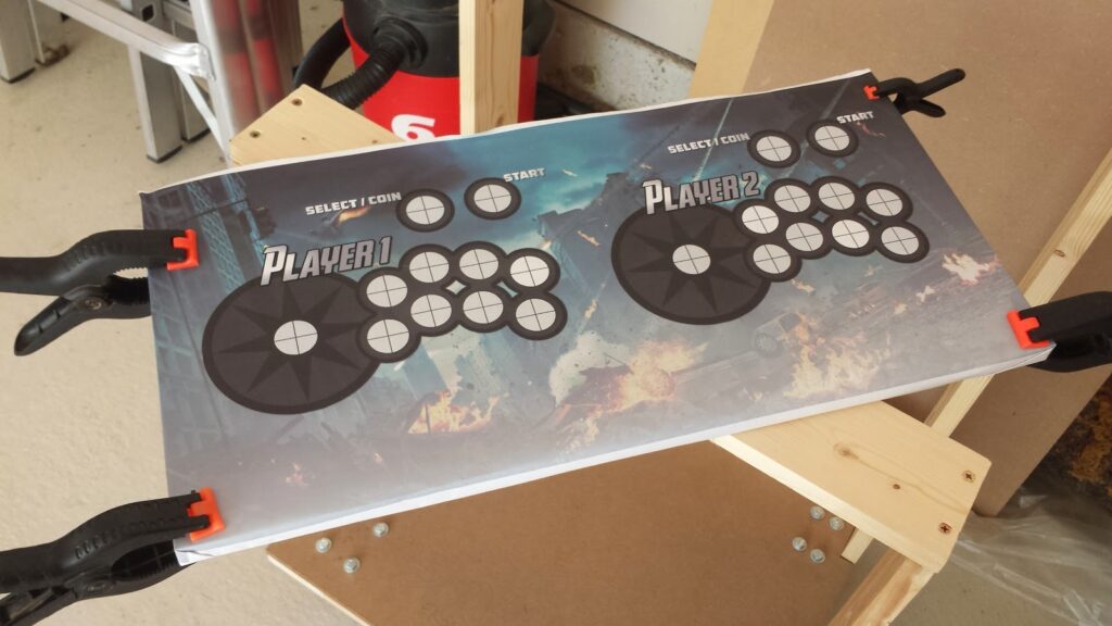
The next step is to prep the top panel for joysticks and buttons. I printed a full size version of my control panel graphics, and clamped them to the top piece.
Then I center punched all of the holes. I want these holes to be drilled as accurately as possible, so I’m taking my time.
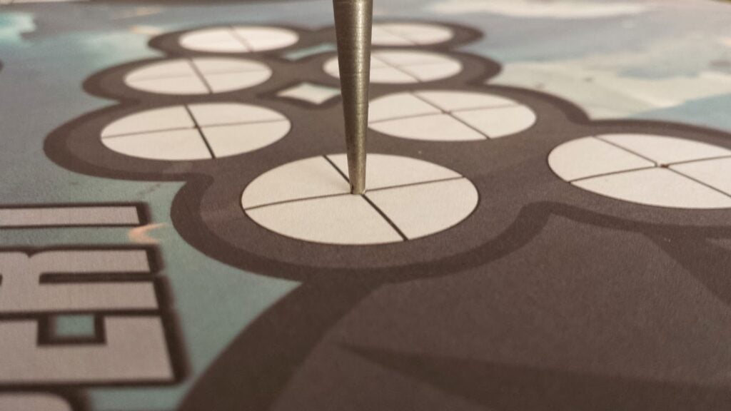
With the holes center punched, I removed the graphic template, and used a small drillbit to drill pilot holes.
Now to drill the holes for the buttons and joysticks using a 1-1/8″ forstner bit. I started with one of the joystick holes, since any mistakes will be covered up by the joystick washer. After drilling a couple holes, I noticed that the bit was tearing chunks out of the underside as the bit came through the MDF. So, I started drilling about 1/4 of the way through the bottom first, then flipping the board over and drilling through the top. This seemed to go more smoothly.
For the joystick attachment, I needed to rout out part of the underside for the joystick mounting plate, because un-routed 3/4″ MDF would only leave a tiny nub of joystick sticking out. First, I drew a square that matched the size of the joystick’s mounting plate, centered on the joystick pilot hole I’d drilled. I actually marked out the area I needed to rout BEFORE I drilled the 1-1/8″ holes (and after I’d drilled the pilot holes). This is because it’s a lot easier to find the center of a tiny drilled hole than a 1-1/8″ hole. Then I simply routed out the area inside the square that I drew. You can either do this with a fancy template, or you can just do it by hand (since nobody will see the underside of your control panel anyways).
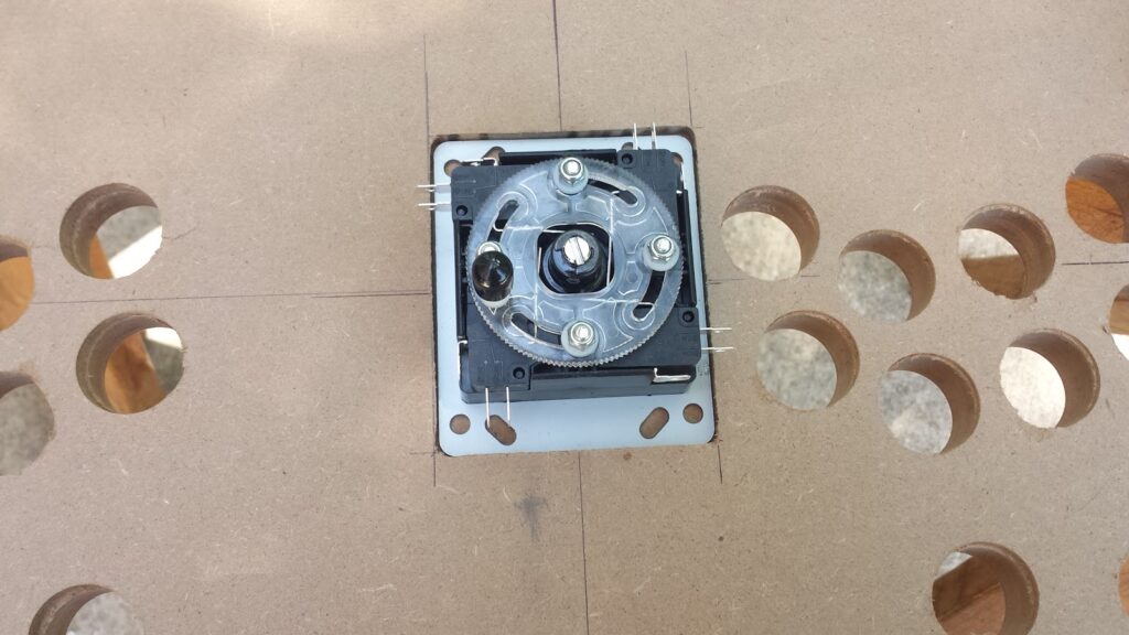
Unfortunately, because I didn’t drill my pilot holes with drill press, where they exited on the underside was just slightly off-center from the intended locations. Luckily, it wasn’t enough to be noticeable up against the art.
Once everything is drilled, I filed the front two corners so they were rounded, and then used my router to create a T-molding slot around the front & side edges of the control panel (more details on how to do this in the “Putting It All Together” post that’s coming up), and primed/painted the control panel black.
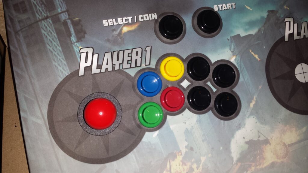
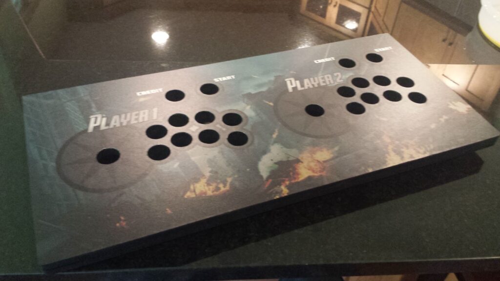
My control panel art was ordered from GameOnGraphix, along with my admin panel art. I created my own art in GIMP, and used their custom design service. [Click here to download the GIMP art file for my control panel] The polycarbonate-coated material they use is terrific for this application, and it was easy to apply. The art is basically a big sticker. Peel off the back, and stick it to the control panel. I lined up the holes from the underside by shining a light through the art to make sure everything was in place. It was slightly off-center when I first started to applied it, but I was able to peel it up and reapply it with no problems.
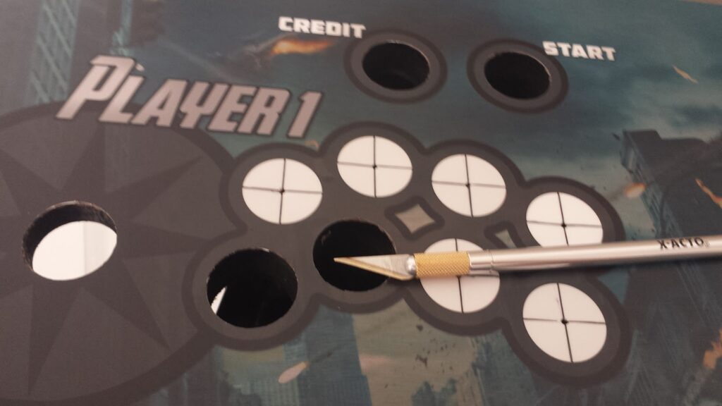
Once the art was applied, I used a sharp X-Acto knife to cut around the edges and inside the button/joystick holes.
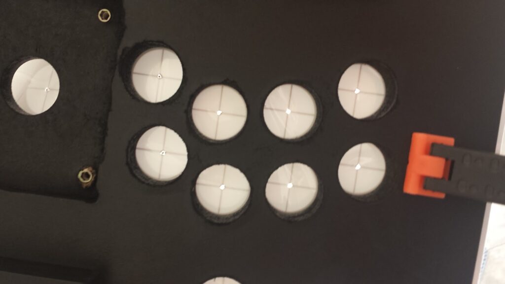
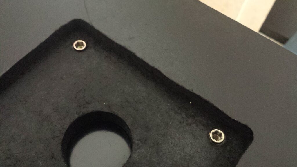
On the underside, I carefully aligned the joysticks where I wanted them to be, and marked where the screw holes needed to be placed. Then I drilled my 0.4″ deep holes (carefully, because the wood is only 0.5″ inch thick here) and inserted EZ-Loks to secure the joysticks.
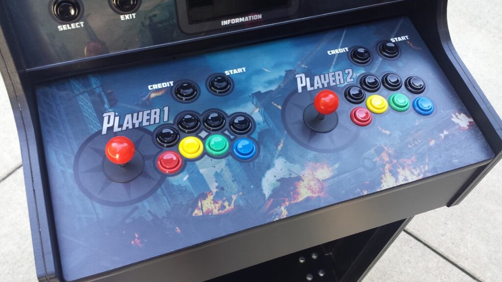
Now to attach all of the buttons and joysticks permanently. My buttons and joysticks were all bought from GroovyGameGear. The buttons are Arcade PRIME buttons. I splurged on “premium” micro-switches for the main 8 buttons for each player (GGG no longer sells the “premium” switches, it appears), but they were louder than the standard switches. So, I kind of wish I’d stuck with all standard switches. Leaf switches would’ve been quieter yet. The joysticks are OMNI2 joysticks which can be switched between 4-way (old games like Pacman only had up/down/left/right movement) and 8-way mode. Because essentially any game with a second joystick was an 8-way game, player two’s joystick is permanently in 8-way mode (I contacted GGG and they gave me a $10 discount to get it this way).
The joysticks are screwed into place with screws and EZ-Loks. The buttons are simply hand-tightened using the nuts that come with them (I bought a fancy nut-tightening tool for the buttons, but it was totally unnecessary).
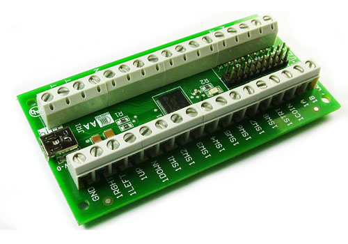
The wiring isn’t particularly difficult, but it was tedious and very time-consuming. All of my controls interface with the computer running the arcade cabinet using an IPAC-2. You can either buy these directly from Ultimarc; or in my case through FocusAttack, which saved quite a bit of money on shipping. You could also try one of GGG’s encoders, the cheaper Xin-Mo encoder (found commonly on eBay), or one of the much cheaper (but much more complicated to set up) Arduino Leonardo boards.
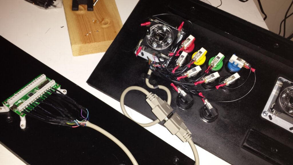
My control panel is actually detachable, so I needed to be able to easily plug/unplug all of the wiring. I did this by wiring everything through M/F parallel cables (one for each player). I cut the cable in half and wired the individual wires from one end into the buttons, and the corresponding-colored wires from the other end into the IPAC. Then I plug it all in by connecting the male and female ends of the cable.
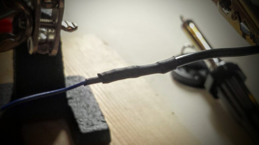
Unfortunately, the wires inside the parallel cables are ridiculously thin, so I needed to solder a short length of thicker 22AWG wire to each wire so I could hook it up to the IPAC’s screw terminals and into the quick disconnects attached to the buttons/joysticks.
At this point, all I needed to do was attach the T-molding (again, more detail on this in the next post; and you can see the T-molding applied in the photo at the very top of this post). I thought I’d need magnets or a latch to keep the control panel in place, but it was clear that I didn’t need any of this once I got everything assembled.
Hi,
Wonderfull work and quite good explained. I love that artwork but I was no able to found It at Gameongraphics. May you tell me the model?
Thanks a lot
Thanks! I actually created the art from scratch using the GIMP photo editing software.
Here's a link to my artwork. (Note, this is a big file — about 175MB)
And here's the link to GoG's page where you can order it.
You first need to export it as a TIFF Image. It is designed to print at 25" x 12.25" at 300dpi (there is some image bleed — the actual control panel size is 24" x 11.25", and there are cut marks on the edges to help you line it up).
What kind of paper did you used to print your artwork?
Control panel & admin panel are polycarbonate-coated vinyl from GameOnGraphix. Side art is black-adhesive vinyl from Souldraw.