Arcade Cabinet: Putting It Together

I’ll preface this part with a warning. If I did it again, I don’t think I’d do it this way.

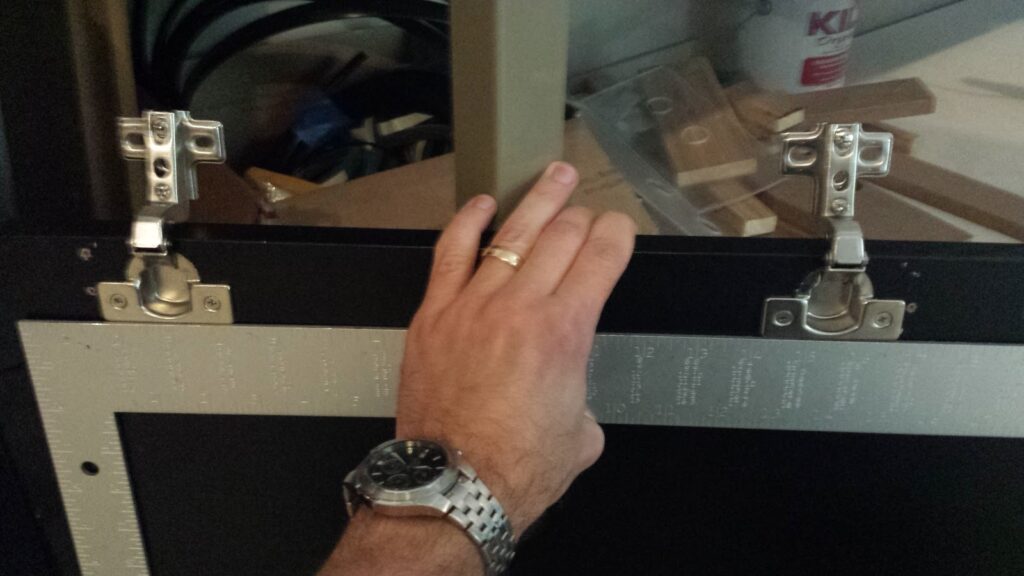
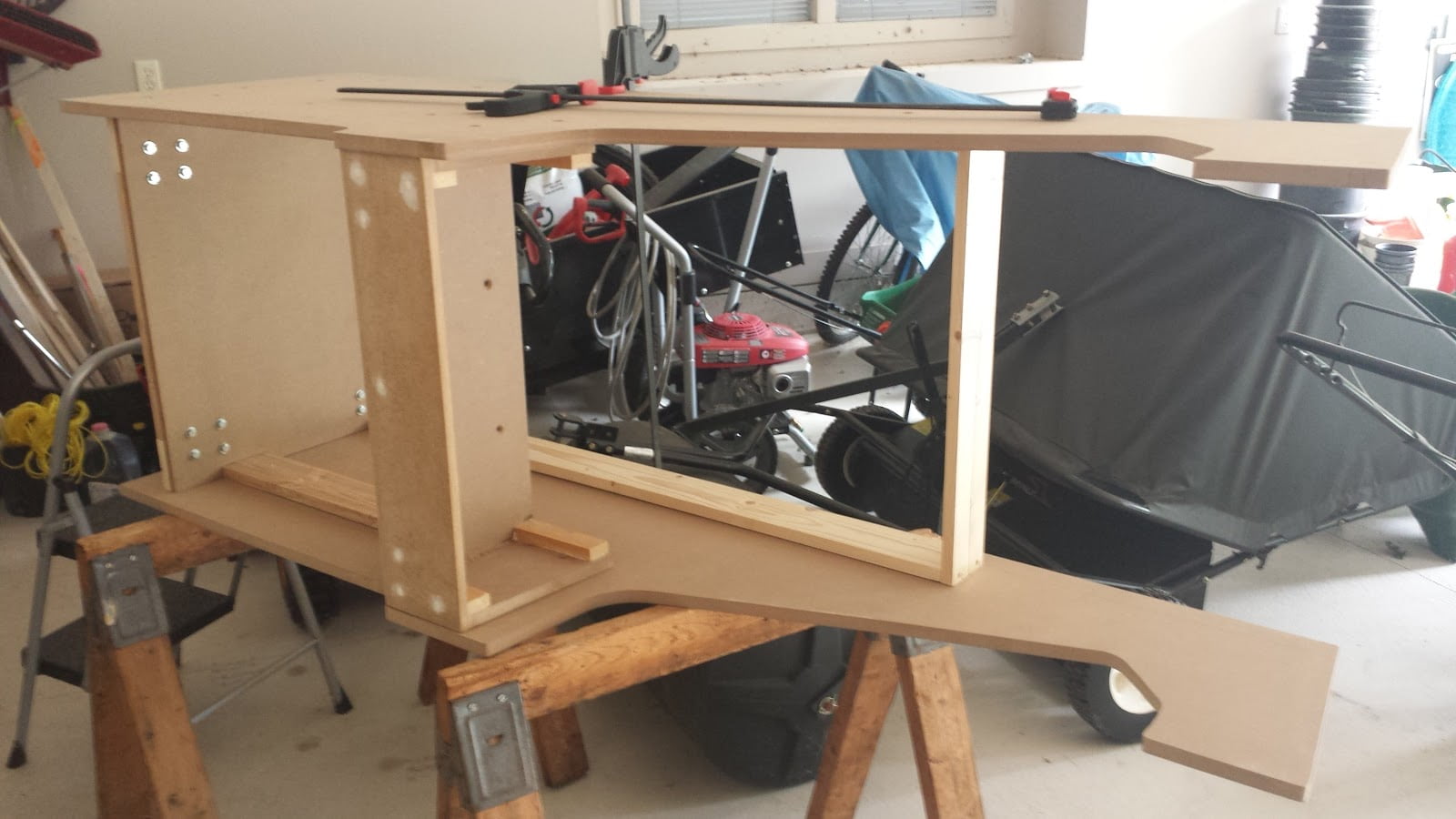
The first thing I did was stack the frame, control panel, and the sides together, then I glued & screwed them together.  Then I attached each individual panel I’d previously built, along with furring strips to secure them in place.

If I do it again, my first step would be to attach the furring strips to both side pieces, and ensure that they are placed symmetrically on both sides.  The problem I ran into was that it was difficult to perfectly line up the furring strips on both sides.  On my final assembly, I have some panels that are slightly crooked.  I’d guess that I might be the only person to notice it, but it’s annoying nonetheless.

For my assembly, I countersunk and screwed each piece into its respective furring strip from the outside.  Then I had to fill & sand each screw hole.  I’m sure other people could find more intelligent ways to do this without needing to fill dozens of screw holes.

Rear view of a partly-assembled arcade cabinet.  The cabinet is primed with white primer, and has 12 small ventilation holes drilled into it
Rear view. I used the button-hole drill bit to add ventilation holes.

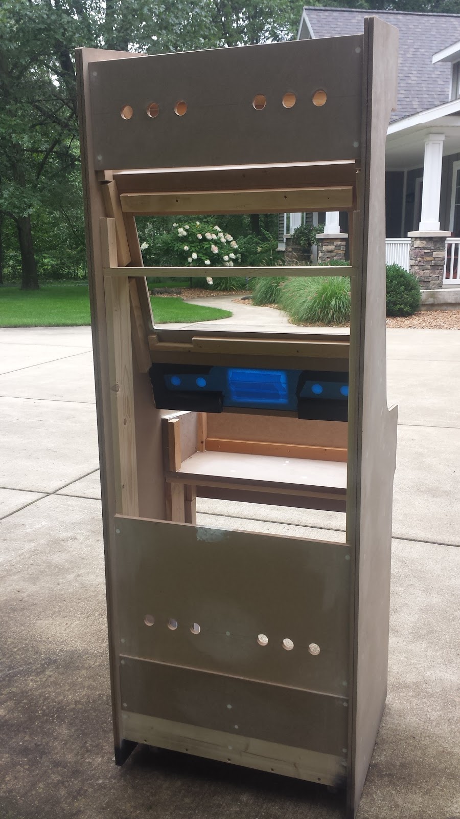
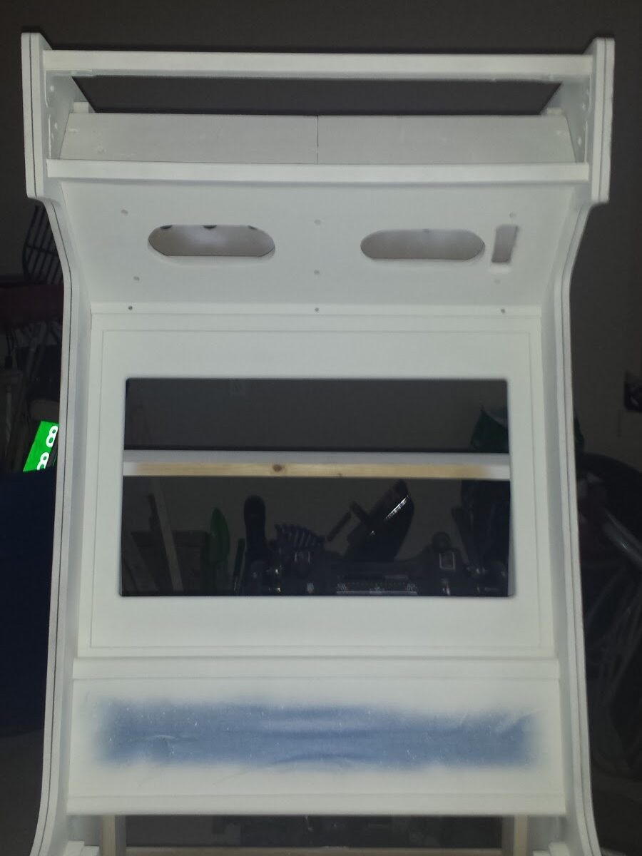
There’s a computer living inside the cabinet, and computers create heat.  So, I also made sure to provide a bit of ventilation.

Front view of a partially assembled arcade cabinet.  Screw holes have been filled & sanded, and painters tape covers the administration panel & inside bottom surface.
Front view. Assembled and prepped for painting.

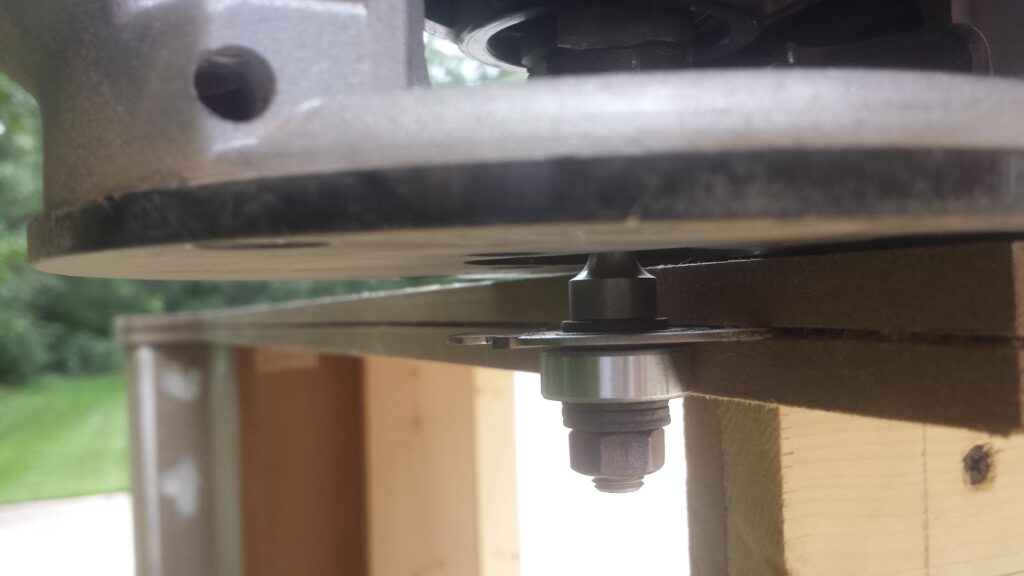
Once everything was assembled, I also routed the slot for the T-Molding.  I used a 1/16″ width & 9/16″ depth bit.  Because my router was old & rickety, I had to constantly keep an eye on where the slot was being routed, since my bit wanted to keep walking out of the collet.

Close-up view of using a handheld router to cut a T-molding slot in an arcade panel side panel.
Routing the T-Molding Slot

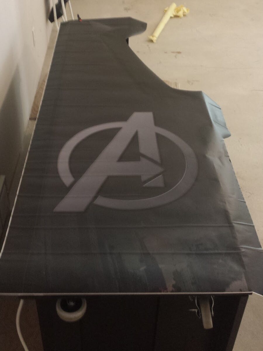
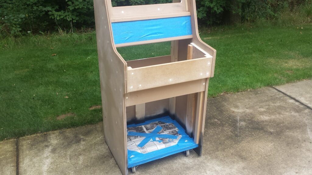
I had previously attached the artwork to the admin panel, so I made sure to tape this off before painting the entire cabinet.  I also previously painted the base.  I don’t know why I previously painted the base. ¯_(ツ)_/¯

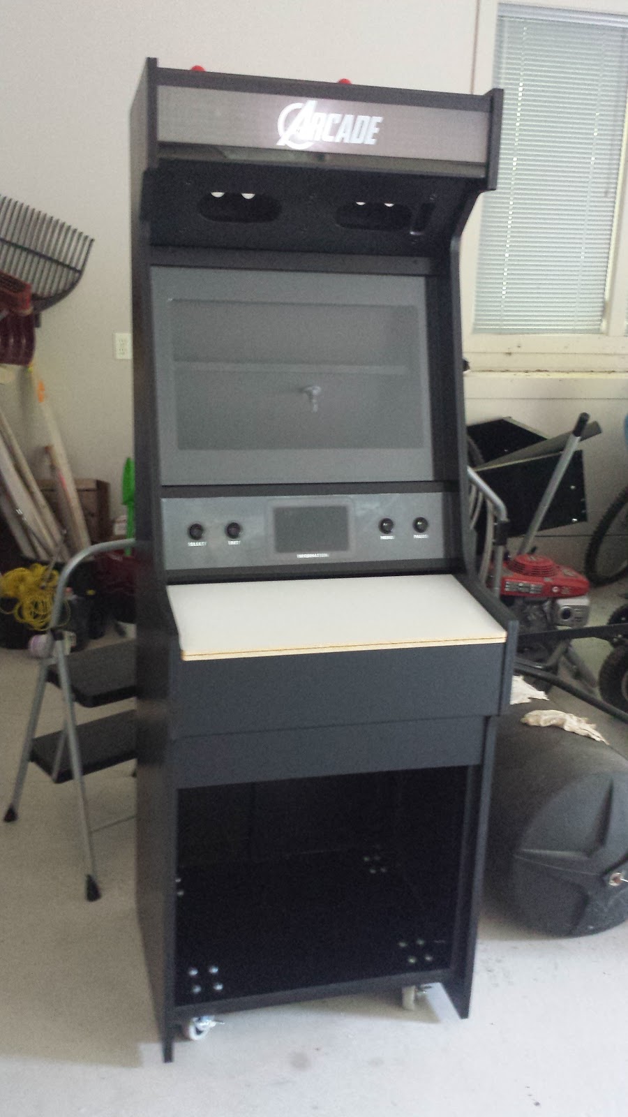
With everything prepped & assembled, I first primed the entire cabinet with Kilz primer…

Top half of arcade cabinet, with primer applied

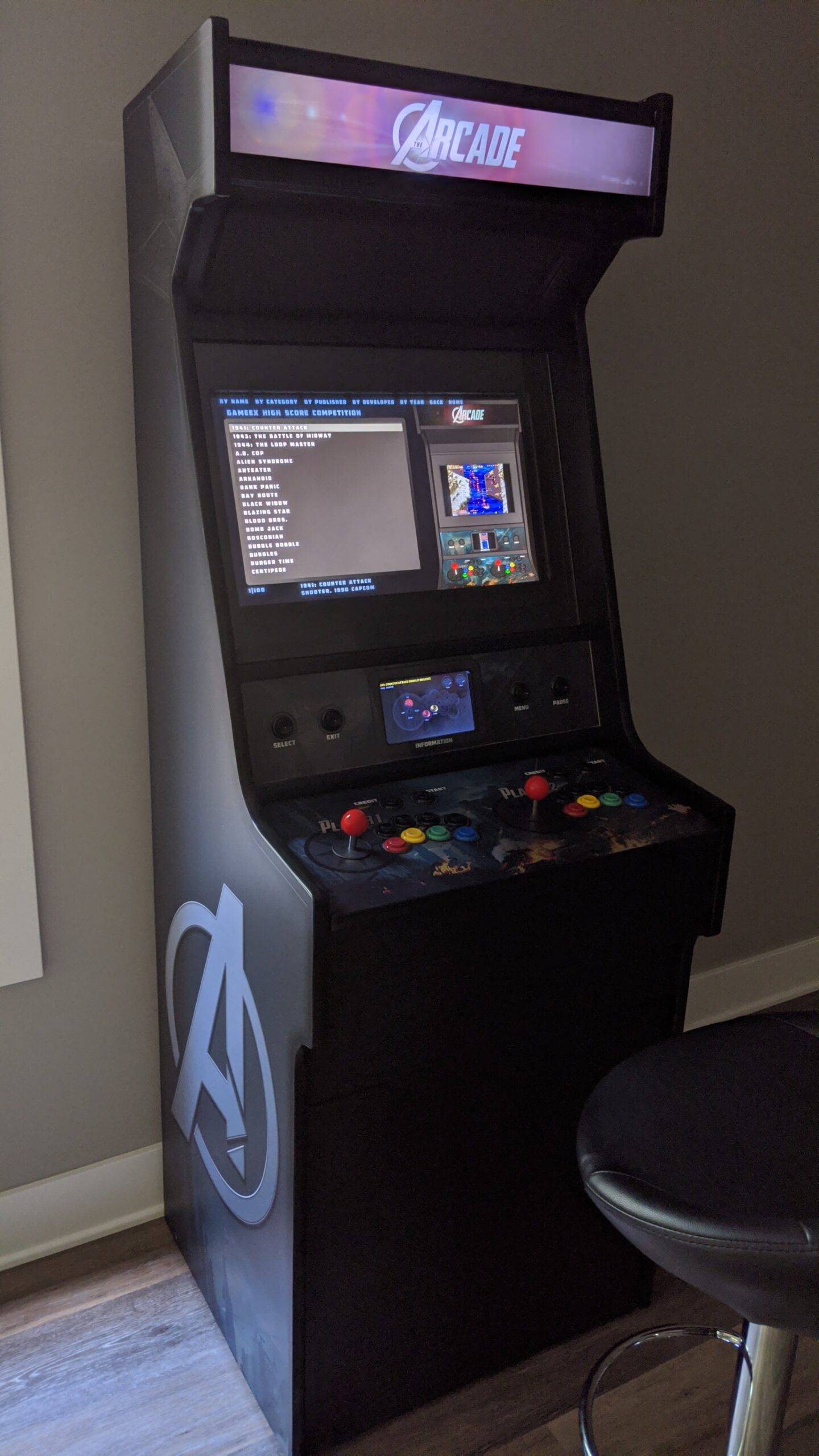
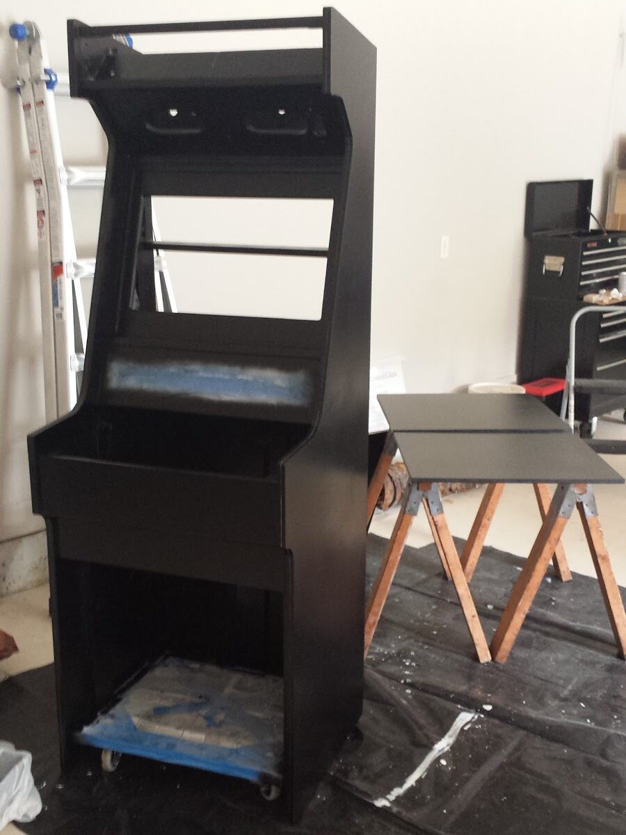
…and then I painted it with two coats of Rustoleum black satin paint.  I chose Rustoleum because it’s enamel & not a latex paint, which means it’s more durable once it dries.  Also of note: when painting & priming, I used foam rollers for the easy-to-paint areas, and a spray can for the not-so-easy areas with lots of edges & corners.

Arcade cabinet, with first coat of black satin paint applied

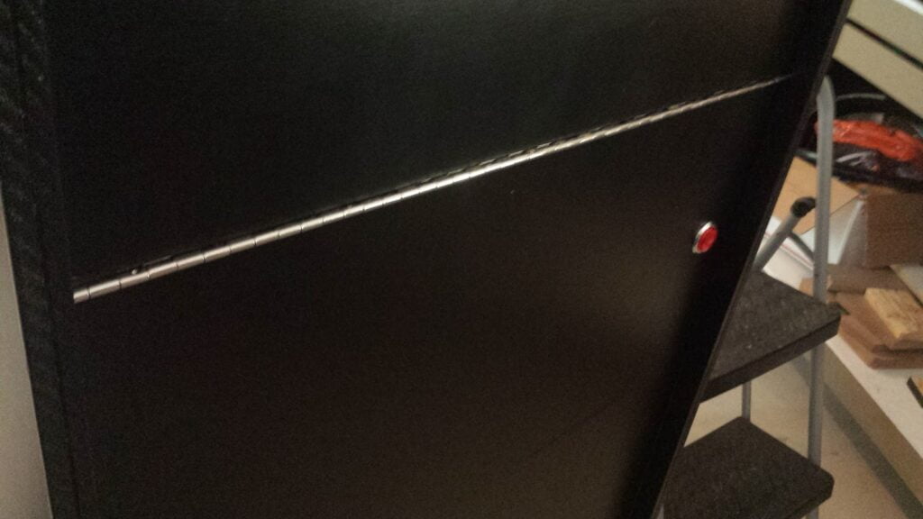
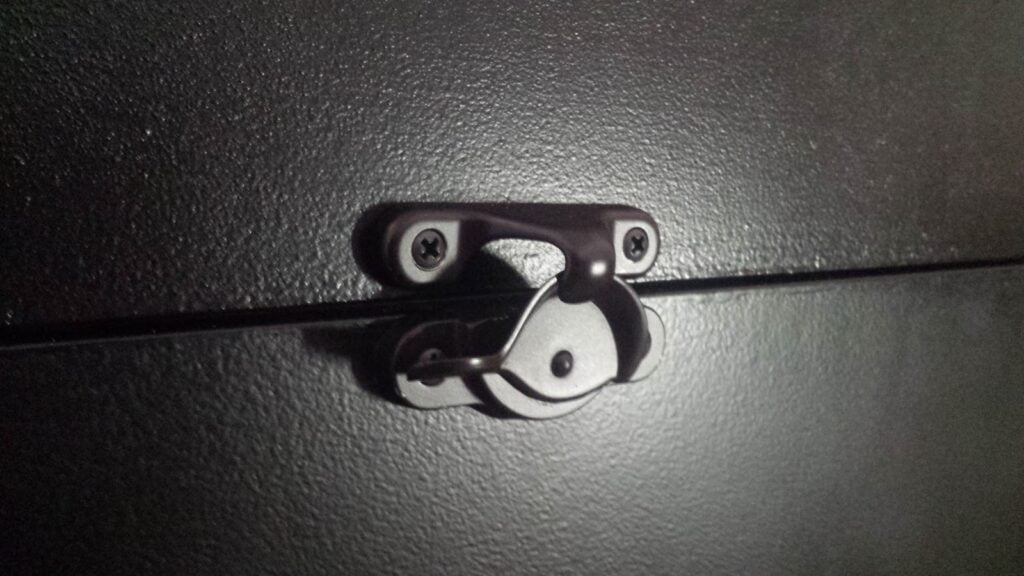
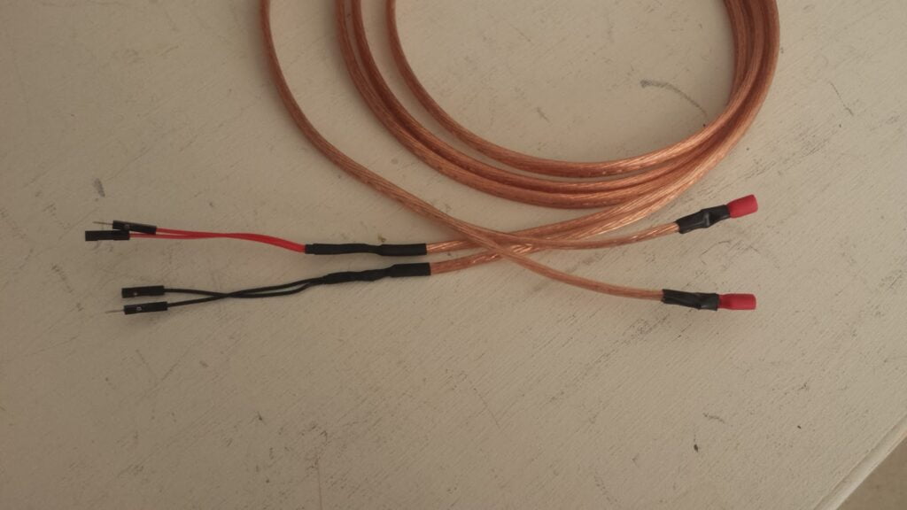
Below is a grab-bag of random features I included in my design:

Arcade control panel stored on top of arcade cabinet
The control panel is removable and can be placed on top of the cabinet.

Arcade cabinet, with a blank white panel installed where the controls would usually be
I included a plain flat version of the control panel to allow mouse & keyboard gaming.  This also fits on top of the cabinet, and is swapped with the button-and-joystick panel.

Rear view of arcade cabinet, showing a piano-hinged access door, and a single red arcade button
The back access door has a bottom-hinge which is a pair of 12-inch piano hinges.  Note the power button.  More on that later…

Close-up of a window sash latch installed to keep the arcade cabinet rear access door closed
A window sash latch is used to keep the back access door closed.

Using a straight-edge to ensure that  a pair of Euro hinges are being installed in proper alignment
The front access door is hinged on a pair of Euro hinges, so the door can be inset from the front of the side panels.

A length of speaker wire.  On one end of each of the pair or wires, male & female patch panel wire has been soldered.  On the other end of each wire, a terminal connector is soldered in place.
The PC inside the cabinet is powered on/off with a regular arcade button.  To do this, I cut male/female patch panel wire in half, and soldered both halves to a single wire.  The other end of the wire has a connector for the arcade button.  The patch panel wires plug directly into the motherboard/case connections for the PC’s power button.  This allows me to power on the PC with the button on the back of the cabinet, or the PC case’s power button.

A sheet of black decorative vinyl adhesive with an Avengers "A" logo is laid loosely on the side of the arcade cabinet, ready for installation
The sideart is printed on black self-adhesive vinyl from Souldraw.com. I used this guide to install the art. 

Finished arcade cabinet, powered up with the GameEx frontend visible on the screen.
A shot of the final product in action.

Leave a Comment